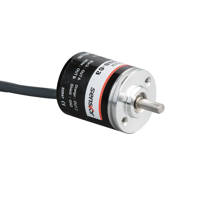
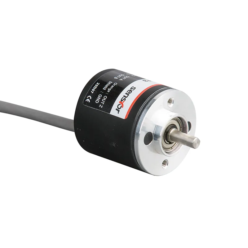
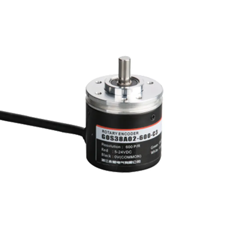
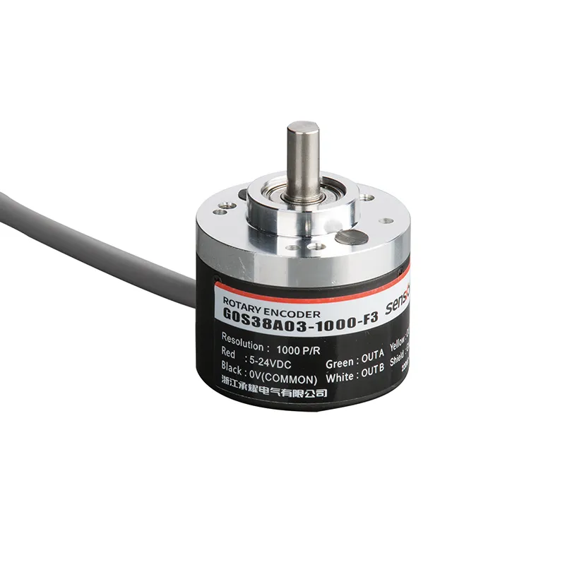
An incremental rotary encoder is a feedback device that converts rotational movement into electrical output signals. Depending on its configuration, an incremental encoder can provide information about rotational position, speed, direction, and pulse count to a control system.
Incremental rotary encoders are widely considered for industrial machinery because their output signals can be processed by controllers, PLCs, drives, and other automation equipment. Selecting the correct encoder requires more than choosing a pulse-per-revolution value. Electrical output, maximum speed, shaft dimensions, mounting, environmental conditions, and controller compatibility should also be evaluated.
An incremental rotary encoder measures rotational movement by producing electrical pulses as its shaft rotates.
Unlike an absolute encoder, an incremental encoder generally provides relative movement information rather than a unique absolute position value for every shaft position.
The control system can use the encoder’s output to determine:
Rotation speed
Rotation direction
Relative position
Distance or movement
Pulse count
Motion timing
An incremental rotary encoder is normally mounted to a rotating shaft, motor, machine mechanism, or other moving component.
As the shaft rotates, the encoder generates output signals. The receiving controller interprets these signals according to the encoder’s output configuration.
This makes the incremental rotary encoder an important feedback component in many motion-control systems.
How Does an Incremental Rotary Encoder Work?
The operating principle of an incremental rotary encoder is based on generating electrical signals corresponding to shaft rotation.
As the encoder rotates, its sensing mechanism produces pulses. The number and frequency of these pulses provide information about movement.
For example:
More pulses over a given period indicate more movement.
Higher pulse frequency indicates higher rotational speed.
The relationship between signal phases can indicate direction.
An index signal, when available, can provide a reference point.
The receiving controller processes the encoder signals and uses them as feedback for the machine.
The exact sensing technology can vary between encoder designs.
A and B Phase Signals
Many incremental rotary encoders use two output channels commonly called A and B.
These signals are phase-shifted from each other.
The control system can analyze the phase relationship between A and B to determine the direction of rotation.
This configuration is often called quadrature output.
For example, when the shaft rotates in one direction, A may lead B. When it rotates in the opposite direction, B may lead A.
The controller can therefore use the signal sequence to distinguish clockwise and counterclockwise movement.
Z Index Signal
Some incremental rotary encoders also provide a Z or index signal.
The Z signal can provide a reference pulse once per revolution, depending on the encoder design.
An index signal can be useful for applications that need a repeatable reference position.
Whether an application requires A, B, Z, or another output configuration depends on the control architecture.
Incremental Rotary Encoder Resolution
Resolution is one of the most important specifications when selecting an incremental rotary encoder.
For many incremental encoders, resolution is specified in pulses per revolution (P/R).
For example, an encoder rated at 1,000 P/R generates 1,000 output pulses per revolution on the specified channel, depending on the manufacturer’s definition.
Higher P/R does not automatically mean that an encoder is better for every machine.
For an incremental encoder, a basic output-frequency calculation can be expressed as:
Output frequency = P/R × RPM ÷ 60
For example, at 1,000 P/R and 600 RPM:
1,000 × 600 ÷ 60 = 10,000 pulses/second
If the encoder has a much higher P/R value, the resulting signal frequency will also increase at the same RPM.
Therefore, engineers should evaluate the encoder’s resolution and the receiving controller’s input-frequency capability together.
Incremental vs Absolute Rotary Encoder
The difference between an incremental rotary encoder and an absolute encoder is important during product selection.
Feature
Incremental Rotary Encoder
Absolute Rotary Encoder
Feedback type
Relative movement
Absolute position information
Typical output
Pulses/signals
Position code or digital interface
Position after power loss
Usually requires reference or tracking
Can retain position information depending on design
System complexity
Often straightforward
Can involve more advanced interfaces
Common consideration
Speed, direction, relative position
Absolute position
Application suitability
Depends on machine architecture
Depends on machine architecture
An incremental encoder can be a practical option when the control system is designed to count pulses and determine movement from the encoder’s signals.
An absolute encoder may be considered when the machine requires absolute position information.
The correct choice depends on the complete system rather than the encoder type alone.
Applications of Incremental Rotary Encoders
An incremental rotary encoder can be used in a wide range of industrial applications.
Industrial Automation
Automation equipment may use incremental encoder feedback for motors, conveyors, rollers, and other rotating components.
The encoder provides movement-related signals to a PLC, controller, or drive.
For an OEM or industrial purchasing inquiry, provide information such as:
Application
Encoder type
Required P/R
Maximum RPM
Output type
Supply voltage
Shaft dimensions
Mounting dimensions
Connector requirements
Environmental conditions
Required quantity
Providing these details can make technical evaluation more efficient.
FAQs About Incremental Rotary Encoders
What is an incremental rotary encoder?
An incremental rotary encoder is a feedback device that converts rotational movement into electrical pulses or signals. A control system can use these signals to determine relative position, speed, direction, or movement.
How does an incremental rotary encoder work?
As its shaft rotates, an incremental encoder generates electrical output signals. The number and frequency of the signals provide movement information, while multiple signal channels can be used to determine rotational direction.
What does P/R mean on an incremental encoder?
P/R generally means pulses per revolution. It describes the number of pulses generated for each revolution according to the manufacturer’s specified measurement method.
What is the difference between an incremental and absolute encoder?
An incremental encoder generally provides relative movement information through output pulses, while an absolute encoder provides position information associated with the shaft’s absolute position. The appropriate type depends on the control system and application.
Can an incremental rotary encoder measure speed?
Yes. A control system can determine rotational speed by measuring the frequency of encoder pulses over time.
Can an incremental rotary encoder detect direction?
Many incremental encoders use two phase-shifted channels, commonly A and B, allowing the controller to determine rotational direction from their phase relationship.
What is the Z signal on an incremental encoder?
The Z or index signal can provide a reference pulse associated with a particular shaft position, commonly once per revolution depending on the encoder design.
How do I choose the resolution of an incremental rotary encoder?
Choose the resolution based on the machine’s feedback requirements, rotational speed, required movement resolution, and controller input capability. Higher P/R is not automatically better for every application.
Can incremental rotary encoders be used with PLCs?
Yes, when the encoder’s electrical output is compatible with the PLC input and the PLC can process the encoder’s signal frequency.
Can incremental rotary encoders be used for servo motors?
They can be used in servo-related applications when the encoder’s feedback specifications and electrical interface are compatible with the servo motor and drive system.
Where can I find industrial rotary encoder products?
An incremental rotary encoder converts rotational movement into electrical feedback signals that can be processed by industrial control systems.
When properly selected, an incremental encoder can provide useful information about speed, direction, relative position, and movement. However, choosing the right model requires a complete evaluation of resolution, output signal, supply voltage, maximum speed, mechanical dimensions, environmental conditions, and controller compatibility.
For OEMs and machine builders, supplier capabilities should also be considered. Technical documentation, sample support, customization, production capacity, and technical communication can all affect the encoder selection process.
Before purchasing an incremental rotary encoder, define the machine’s requirements and compare the encoder’s specifications with the actual control system.
Table of Contents Introduction China encoder supplier companies have become important partners in the global automation industry. A professional China encoder supplier provides high-quality rotary encoders, motion feedback devices, and industrial automation solutions for manufacturing, robotics, CNC machinery, and packaging systems. Today, businesses worldwide choose a reliable China encoder supplier because of competitive pricing, advanced […]
📊 Comprehensive Outline for “heavy duty encoder” Heading Level Topic H1 Heavy Duty Encoder: 15 Powerful Benefits for Industrial Performance H2 Introduction to Industrial Encoders H2 What Makes an Encoder “Heavy Duty” H2 Working Principle Explained H2 Types of Industrial Encoders H2 Key Components and Build Quality H2 Applications in Modern Industries H2 Advantages in […]
We use cookies to enhance your browsing experience, serve personalised ads or content, and analyse our traffic. By clicking "Accept All", you consent to our use of cookies.